
Mô tả sản phẩm
Series 3272 … CR
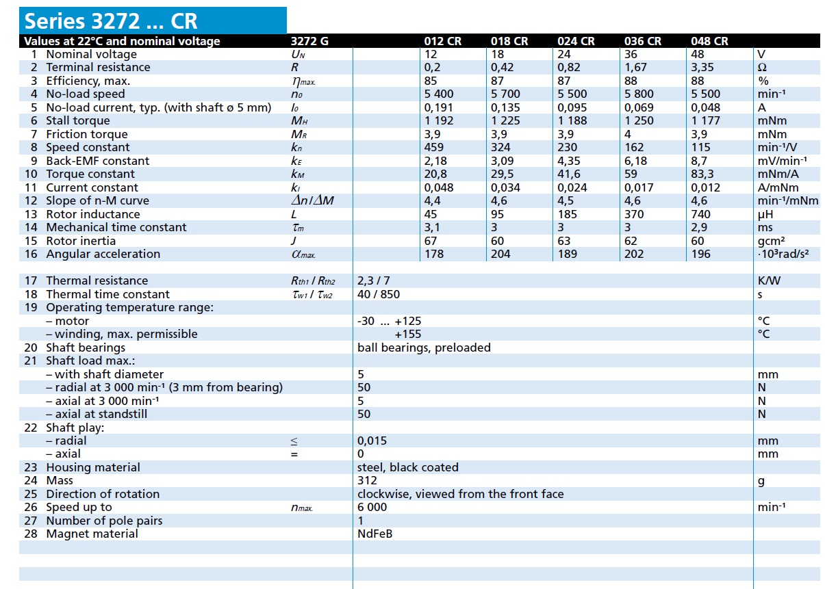
Values at 22°C and nominal voltage 3272 G 012 CR 018 CR 024 CR 036 CR 048 CR
1 Nominal voltage
UN 12 18 24 36 48 V
2 Terminal resistance
R 0,2 0,42 0,82 1,67 3,35 Ω
3 Efficiency, max.
ηmax. 85 87 87 88 88 %
4 No-load speed
n0 5 400 5 700 5 500 5 800 5 500 min –¹
5 No-load current, typ. (with shaft ø 5 mm)
I 0 0,191 0,135 0,095 0,069 0,048 A
6 Stall torque
MH 1 192 1 225 1 188 1 250 1 177 mNm
7 Friction torque
MR 3,9 3,9 3,9 4 3,9 mNm
8 Speed constant
k n 459 324 230 162 115 min –¹/V
9 Back-EMF constant
k E 2,18 3,09 4,35 6,18 8,7 mV/min –¹
10 Torque constant
k M 20,8 29,5 41,6 59 83,3 mNm/A
11 Current constant
k I 0,048 0,034 0,024 0,017 0,012 A/mNm
12 Slope of n-M curve
Δn /ΔM 4,4 4,6 4,5 4,6 4,6 min –¹/mNm
13 Rotor inductance
L 45 95 185 370 740 μH
14 Mechanical time constant
τm 3,1 3 3 3 2,9 ms
15 Rotor inertia
J 67 60 63 62 60 gcm²
16 Angular acceleration
αmax. 178 204 189 202 196 ·103rad/s²
17 Thermal resistance
Rth1 /
Rth2 2,3 / 7 K/W
18 Thermal time constant
τw1 /
τw2 40 / 850 s
19 Operating temperature range:
– motor -30 … +125 °C
– winding, max. permissible +155 °C
20 Shaft bearings ball bearings, preloaded
21 Shaft load max.:
– with shaft diameter 5 mm
– radial at 3 000 min– ¹ (3 mm from bearing) 50 N
– axial at 3 000 min-¹ 5 N
– axial at standstill 50 N
22 Shaft play:
– radial ≤ 0,015 mm
– axial = 0 mm
23 Housing material steel, black coated
24 Mass 312 g
25 Direction of rotation clockwise, viewed from the front face
26 Speed up to
nmax. 6 000 min–¹
27 Number of pole pairs 1
28 Magnet material NdFeB
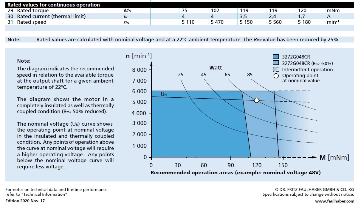
Rated values for continuous operation
29 Rated torque
MN 75 102 119 119 120 mNm
30 Rated current (thermal limit)
I N 4 4 3,5 2,4 1,7 A
31 Rated speed
nN 5 110 5 470 5 150 5 560 5 180 min –¹
M [mNm]
n [min -1
]
30 90 12060 1500
3 000
0
6 000
2 000
8 000
5 000
1 000
7 000
4 000
UN
3272G048CR
3272G048CR (Rth2 -50%)
Watt
85654525
Recommended operation areas (example: nominal voltage 48V)
Intermittent operation
Operating point
at nominal value
Note:
The diagram indicates the recommended
speed in relation to the available torque
at the output shaft for a given ambient
temperature of 22°C.
The diagram shows the motor in a
completely insulated as well as thermally
coupled condition (Rth2 50% reduced).
The nominal voltage (U N ) curve shows
the operating point at nominal voltage
in the insulated and thermally coupled
condition. Any points of operation above
the curve at nominal voltage will require
a higher operating voltage. Any points
below the nominal voltage curve will
require less voltage.
Note: Rated values are calculated with nominal voltage and at a 22°C ambient temperature. The
Rth2 value has been reduced by 25%.


Đánh giá
Chưa có đánh giá nào.